

Description
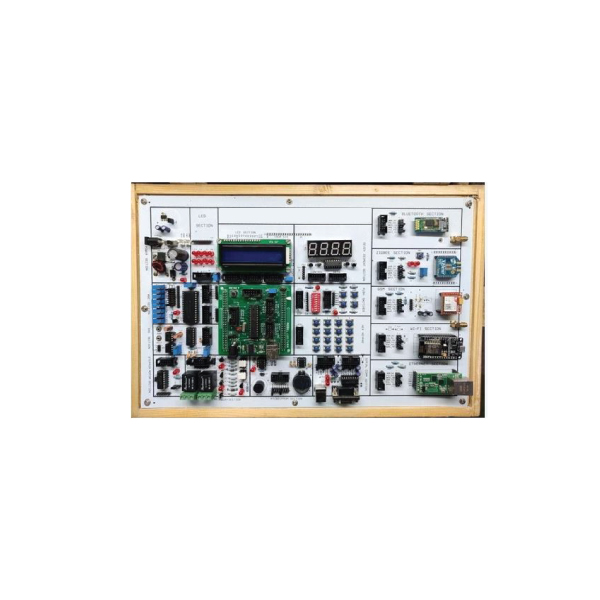
 SPECIFICATIONS OF BASIC AND POWER ELECTRONICS LAB TRAINER:
 Industrial-standard sensors and transducers
With USB interface Open-ended design,
ideal for expansion Offer a sensing data
acquisition software Specifications:

 Main Unit Of BASIC AND POWER ELECTRONICS LAB TRAINER:
1. Power Supply Unit
Fixed DC power supply Output voltage : +5V,-5V, +12V, -12V
Max. output current : +5V 3A, -5V 0.3A, +12V 1.5A, -12V 0.3A(3) With output overload protection.

2. AD Converter : 1x12-bit ADC.
Input voltage range : 0 to +5V.
Time pulse frequency : 3.58 MHz Control
signals : Status, pole, over range indication

3. Interface Port USB interface : Type B

4. D A Converter : 1 x 12-bit DAC Analog
output & control OUT+ : +DC OFFSET 0V
+4.096V unipolar OUT- : -DC OFFSET 0V -4.096V unipolar.
OUT BP : DC OFFSET-2.048V +2.048V bipolar

5. Preset LevelMax. value : 4095.
6. Status Display & DCV Input voltage
measurementa. a. Range : 2000mV, 20V
b. Accuracy : ±0.0 of reading + 4 counts
c. Input impedance : 10MΩ
d. Display : 4 digits.
7. Mode Selector Manual or single-chip
8. Buzzer: Maximum input signal voltage :+12V.
9. Micro controller Signals 5 Control line outputs
10. Model Holder : X4.
11. Potentiometer : 100k ohm B-type.
12. Comparator V-,V+ input, Vo output
13. Differential amplifier V-,V+ input, Vo output
14. Instrumentation amplifier V-,V+ input, Vo output,

Adjustable gain Experiment Modules:
1. Using 2mm plugs and sockets.
2. Comprehensive experiment manual
3. Modules secured in plastic housings.
4. Connected by 2mm-2mm test leads
5. Dimension : 255 x 165 x 30mm.
6. Circuit symbols, blocks and components printed on the surface of each module
7. Power supplied from LI-ST main unit.

List of Module
Module-1.
1. Photo transistor.
2. Photo interrupter.
3. Magnetic (hall-effect) digital
4. Magnetic (hall-effect) analog

Module-2
1. Pyroelectric detector
2. Reed switch
3. Thermistor
4. Mercury switch

Module-3
1. Limit switch.
2. Vibration switch.
3. Condenser microphone.
4. Dynamic microphone.

Module-4
1. Gas smoke sensor.
2. Ethanol sensor .

Module-5
1. IC (AD590) temperature sensor.
2. Humidity sensor.
(1) Humidity transducer rated voltage : 1 Vp-p AC.
(2) Frequency range : 100Hz to 10KHz.
(3) Temperature range : 0C to 60 C.
(4) Humidity range : 20 percentage RH to 90percentageRH
(5) Impedance : 13 k oham (70percentageRH at 25C)

Module-6
1. Infrared TX or RX sensor
(1) Infrared transmitter : Emission intensity : 12mW sr (I = 50mA)
Emission wavelength : 940nm (IF = 50mA
(2) Infrared receiver : Sensitivity wavelength : 1000nm
2. Ultrasonic TX or RX sensor Norminal frequency : 40KHz

Module-7
1. Pressure sensor 0-7 psi to 0-30 psi pressure ranges
2. Strain gauge
(1) Maximum payload : greater5kg
(2) Terminal resistance : 350 ± 50Ω

Module-8
1. Hall current sensor
(1) Nominal current : ±3A
(2) Current range : ±9A
(3) Output voltage : ±4V, RL equal 10 k Ohms

2. Proximity sensor
(1) Operation voltages : 10 to 30V DC

List of Experiments
1. D A and AD Converters.
2. Characteristics of Sensors.
3. Gas Sensors.
4. AD590 Temperature Transducer .
5. Hall Current Sensor.
6. PT100 Temperature Sensor
7. Humidity Sensor.
8. Strain Gauge.
9. Linear Variable Difference Transformer (LVDT).
10. Photovoltaic Cell.
11. Proximity Switch.
12. Infrared Transducer.
13. Ultrasonic Transducer.
14. Pressure Sensor.
15. VF and FV Converters.
16. CdS Cell.
17. Level Controller .
18. Fiber Optical Communication.
19. Rotation Angle Sensor.
Accessories Of Basic And Power Electronics Lab Trainer:
Connecting jack 2mm & 4mm: 01 Set
Power Cable: 01 no
English Manual & CD: 01 Set


Warranty: 1 years with service and spare parts
Installation, Testing and Commissioning will be performed by our expert engineers
We will arrange a Two -day-long training at the point of delivery and will provide training to at least five participants
Will provide an experiment manual that covers a detailed step-by-step process for conducting each experiment.
Reviews
There are no reviews yet.