

Description
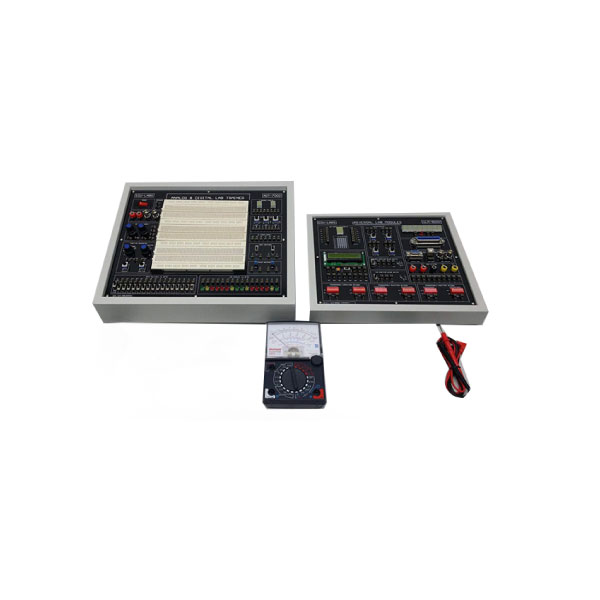
SPECIFICATIONS OF DIGITAL LOGIC LAB TRAINER:
Power Supply
Main Unit Dual DC Power Supply
Voltage range : +5V/1.5A,-5V/0.3A,+-12V/0.3A,
With output overload protection
Adjustable DC Power Supply
Voltage range : +1.5V ~ +15V,Max.
current output : 0.5A,With output overload
protection
Standard Frequency
Frequency : 1MHz,60Hz,1Hz,
Accuracy : +- 0.01% (1MHz),
Fan out : 10 TTL load,Clock Signal Generator,
Frequency : 1Hz ~ 1MHz (6 ranges),1Hz ~ 10Hz,10Hz
~ 100Hz,100Hz ~ 1KHz,1KHz ~ 10KHz,10KHz ~
100KHz,100KHz ~ 1MHz,
Others Specification Of Digital Logic Lab Trainer:
Fan out : 10 TTL load,
Data Switch,-8-bit DIP switch x 2,16-bit
TTL level output
Toggle switch x 4
each with Debounce circuit
Fan out : 10 TTL load,
Pulser Switch
2 sets of independent control output,
Each set with Q
Qft output
pulse width > 5ms
Each set of switch with Debounce circuit
Fan out : 10 TTL load
5 Universal counters, Line Signal Generator
Frequency : 50Hz/60Hz
Output voltage : 6Vrms,With overload
protection,
Thumbwheel Switch : 2-digit,
BCD code output and common point input,
Logic Indicator: 16 sets of independent LED
indicates,
high /low logic state,
Input Impedance : ¬ 100K ohms,
Digital Displays,
2 sets of independent 7-segment LED
display,
With BCD,
7-segment decoder/driver and DP input,
Input with 8-4-2-1,5mm LED displays,
Inch LoInch and Inch HiInch LED display
low/high logic state respectively,
Speaker : 8 ohms,
0.25W speaker with driver circuit
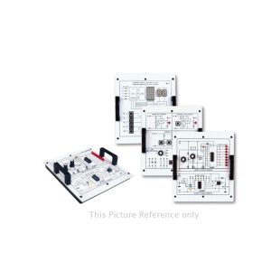
Experiment Modules
1. All 13 modules are equipped with an 8-bit
DIP,
switch for fault simulation.,
2. Solutions for all fault test are listed in the,
experiment manual for user fts reference.,
3. 2mm plugs and sockets are used
throughout, the main unit and all modules.,
4. Comprehensive experiment manual and
instructor fts manual.,
5. Module dimension: (255 x 165 x 30) mm.,
6. Connection plugs are used on the modules
to, prevent accidental damages.,
7. Individual keeping case for each module,
List of Experiments
1. Basic Logic Gates Experiments
(1) Introduction to logic gates and switches,
(2) Logic gates circuits,
(3) Threshold voltage measurement,
(4) Voltage/current measurement,
(5) Basic logic gate transmission delay measurement,
(6) Measurement of basic logic gates characteristics,
(7) Interface between logic gates
2. Combinational Logic Circuits Experiments
(1) NOR gate circuits,
(2) NAND gate circuit,
(3) XOR gate circuit,
(4) AND-OR-INVERT (AOI) gate circuit,
(6) Schmitt gate circuit
(7) Open-collector gate circuits,
(8) Tristate gate circuits,
(9) Half-adder and full-adder circuits,
(10) Half-subtractor and full-subtractor
circuit,
(11) Arithmetic Logic Unit (ALU) circuit,
(12) Bit parity generator circuit,
(13) Encoder circuit,
(14) Decoder circuit,
(15) Multiplexer circuit,
(16) Demultiplexer circuit,
(2) Constructing oscillator circuit with
schmitt gate,
(4) 555 IC oscillator circuit,
(5) Monostable multivibrator circuits,
(6) Constructing dynamic scanning
counterwith single-chip microprocessor,
4. Sequential Logic Circuit Experiments
(1) Flip-flop circuits
(2) J-K flip-flop circuits,
a. Asynchronous binary up-counter,
b. Asynchronous decade up-counter,
c. Asynchronous divide-by-N up-counter,
d. Asynchronous binary down-counter,
e. Synchronous binary up-counter,
f. Synchronous binary up/down counter,
6. Converter Circuit Experiment,
(1) Digital/Analog Converter (DAC) circuit,
a. Unipolar DAC circuit,b. Bipolar DAC circuit,
(2) Analog/Digital Converter (ADC) circuit
,a. 8-bit converter circuit,
b. 3 1/2 digit converter circuit,
Computer-Based Training,
1. Built-in circuit simulation of experiment
modules.,
2. Fault simulation is allowed.,
3. Users can flexibly compare the simulation
analysis,Result with hardware signal output
Accessories Of Digital Logic Lab Trainer:
Connecting Wire: 1 Set
User Manual : 1 Set
Others Accessories
OTHERS:
Brand : Labinnova
Country Of Origin: China
Manufacturing : Assemble In Bangladesh
Warranty: One Year

Reviews
There are no reviews yet.