

Description
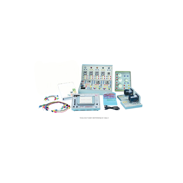
SPECIFICATIONS OF BASIC ELECTRONICS TRAINER:
1. DC POWER SUPPLY
(1) Fixed DC power supply:
a. Voltage range: +/-5V +/-12V
b. Max. Current output: 0.3A
c. With output over-load protection
(2) Dual DC power supply:
a. Voltage range+/-3V~ +/-18V, continuously
adjustable
b. Max. Current output: 1A
c. With output over-load protection
2. AC POWER SUPPLY
a. Voltage range: 9V~0V~9V
b. Max. Current output: 500 m A
c. With output over-load protection
3. SIGNAL GENERATOR
(1) Pulse generator: (TTL level)
a. Frequency range: 1Hz~10KHz / 4 settings,
continuously adjustable
b. Fan out: 10 TTL load
(2) Pulse switches:
a. 2 independent output, TTL level
b. With Q, Q output, pulse width > 5ms
c. Fan out: 10 TTL load
(3) Data switches
a. 8 sets independent control output, TTL
level with De-bounce circuit.
b. Fan out: 10 TTL load
4. FUNCTION GENERATOR
(1) Output waveform: Sine, triangle, square
(2) Output frequency: 10~100KHz/4 settings,
continuously adjustable
(3) Output amplitude: 18Vpp (open circuit)
9Vpp (50 O load)
5. TESTING AND DISPLAY
(1) 3 1/2 digital voltmeter/ammeter
a. DC voltage range: 2V200V
b. DC voltage accuracy: +/-(0.3% of reading
+1 digit)
c. DC current range: 200
(2) Galvanometer
a. Current range 50mA
b. Accuracy Class 2.5
(3) LED indicator
a. 10 sets independent LED indicates high,
low logic state
b. Input impedance: ≥100KΩ
(4) Digital display
a. 2 sets independent 7-segment LED
b. With BCD-7segment decoder/driver and
DP Input
c. Input with 8-4-2-1 code
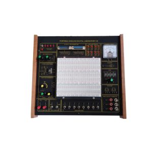
Breadboard: 1680 tie-point breadboard on
top panel can be easily put into and taken
off
Accessories: Experiment manual, connection
leads, connection plugs, breadboard
List of Module:
a. Basic Device Module
b. Basic Electricity Experiment Module
c. Sensor Module(1)
d. Sensor Module(2)
e. Diode, Clipper and Clamper Module
e. Diode, Clipper and Clamper Module
f. Rectifier, Differentiator Integrator Circuit
Module
g. Transistor Amplifier Circuit Module
h. Multi-Stage Amplifier Circuit Module
i. FET Circuit Experiment Module
j. OP Amplifier Circuit Module 1, 2, 3, 4, 5
k. Combination Logic Circuit Experiment
Module 1, 2, 3, 4, 5
l. Sequential Logic Circuit Experiment Module
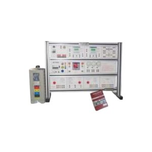
L, 2 m. Low Voltage Electrical Control Module
(3 is required)
n. Single-Phase Motor Module (1 AC 220V)
o. Three-Phase Motor Module (3 220V)
p. Load Unit Module
q. System Transformer
Accessories Of Basic Electronics Trainer Model:
connection plugs
breadboard
Experiment manual
connection plugs
Others:
Brand : Labinnova
Country Of Origin: China
Manufacturing : Assemble In Bangladesh
Training 3 Days
Warranty: One Year

Reviews
There are no reviews yet.